DIY – LM1881 Sync Stripper
This page will show you how to use an LM1881 chip to “strip” the sync information from composite video, for use in an RGBs video signal. You do not need a sync stripper for SCART equipment, but some monitors and BNC switches might require them. Please only use one if you know for a fact you’ll need it.

Please note that the LM1881 outputs TTL-level sync. If you’re going into a device that’s expecting 75 ohm video-level sync (such as ALL SCART equipment), then you’ll need to add a 470ohm resistor to the output line. There’s more info at the bottom of the page and for more information on sync, please see the main sync page.
Parts Needed:
You will need basic tools (more info can be found in the tools section), plus the following items for this circuit:
– Basic tools, such as pliers, tweezers, etc.
– Soldering iron / solder
– Basic soldering skills.
– LM1881M chip, the SOIC version (please see the links to the right for the chip) —>
– One 680K resistor
– Two 0.1uf Capacitors
– One 470 ohm, 1/4 watt resistor (if 75 ohm csync output is needed)
Board Assembly:
This is a fairly easy circuit to build, but there’s a few tricks to make it smaller and easier. Also, this guide assumes you’d like to use a mounting board. You can use this guide if you’d like to solder directly to a chip, but this is a “cleaner” way to make the circuit. I’ll walk you through it step-by-step:
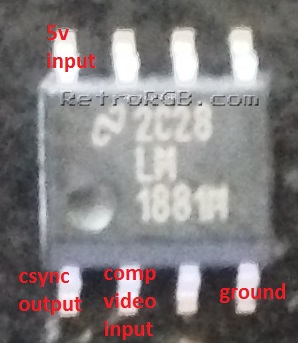
– This is the main LM1881M chip you’ll be using (surface-mount, SOIC version) and it’s relevant pins:
– Start by adding solder to both the chip legs and the pads on the board, by heating the area with your soldering iron and then touching solder to the metal. I got used to doing this on a desk, but using a stand and alligator clips will make it easier:

– After applying solder to both, use pliers or tweezers to hold the chip while you mount it to the board. Once it’s lined up, you should be able to just touch your soldering iron to it and they will solder together:

– Next, you’ll want to use a multimeter to check your solder points. When checking, make sure to touch the pin where it enters the chip, not near the bottom where you may accidentally be making contact with the circuit board’s pads. Then, touch the other tester to the pad that matches it’s input. If a connection isn’t made, you could try adding more solder to the joint between the pad and pin:

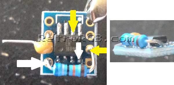
– Add a 0.1uf capacitor to the hole that corresponds with pin 2 (composite video in) on the LM1881M. I suggest using a multimeter to double check that the hole on the board matches the pin on the chip:

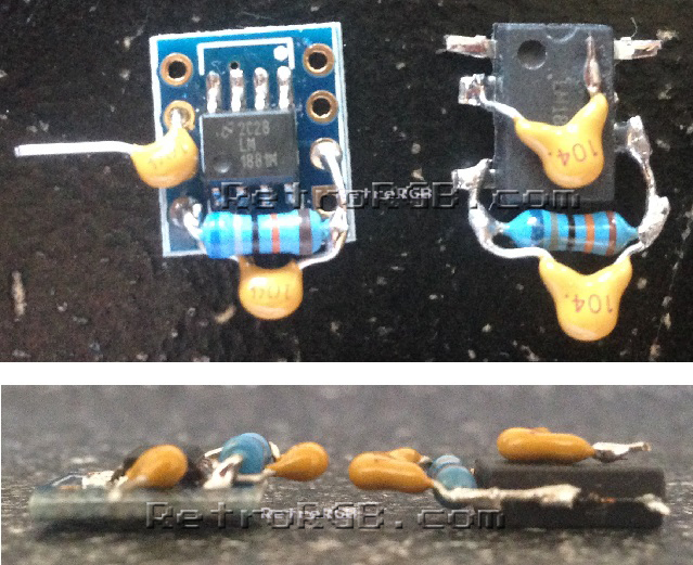
– Then add a 680K resistor to the holes corresponding to the arrows below (once again, I suggest using a multimeter to double check the holes to pins between the chip and board). Also, make sure that the resistor isn’t touching any of the pins on the chip, or touching the other holes on the board. I have mine run above the board to ensure it’s not touching, as shown in the bottom-right picture:
– Next, solder a 0.1uf capacitor to the resistor. I like to solder it as close to the resistor itself as possible, to make sure it’s not touching anything else, or touching to board’s pads.

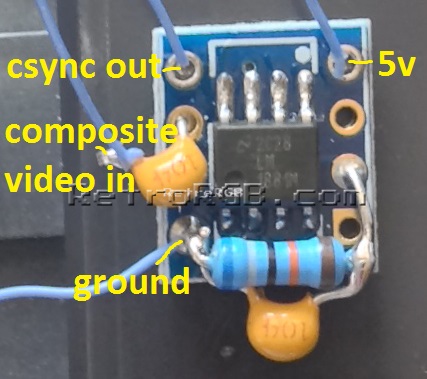
– Finally, solder power and ground, as well as composite video in / csync out:
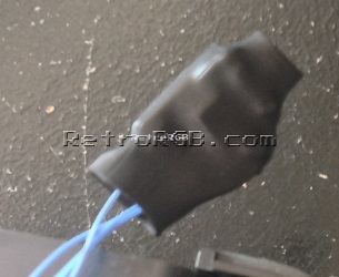
– After you’re done, it’s good to cover the circuit with heatshrink tubing, so you won’t risk shorting it out (or anything else around it).
– That’s it! Overall, it’s pretty easy to make and is a bit smaller then soldering it directly to the chip. I actually fit one of these inside a VGA head for use with equipment that requires TTL-level voltage. Also, it makes for a much cleaner look. That being said, if you prefer the chip-only solution, you can check out this guide:
75 Ohm csync output
Please note that this guide shows you how to build the sync stripper circuit; It does NOT talk about use case scenarios. If you’re plugging this into any SCART device, then you’ll need to add one 470 ohm, 1/4 watt resistor to attenuate the output to 75 ohm video standards. Many RGB monitors accept a wide variety of sync signals, including the TTL sync that this circuit outputs. If you’d like to be safe, just add the extra resistor; It’s literally as easy as just soldering it to the csync output pin.
That’s it! A pretty easy circuit that can really come in handy! If you’ve arrived at this page as part of the RGB Guide, please move along to: what method you’d like to use to display RGB. If not, feel free to head to the main sync stripper page, or check out the homepage for everything else we have to offer.