SNES 1CHIP RGB Amp Bypass – DIY Amp
All model 1 SNES systems (including the 1CHIP) output RGB without a modification. This page shows how to bypass the stock output with a THS7316.
WARNING: This mod is only for the 1CHIP systems, as the motherboards for different SNES revisions will be different and the pins will not match up. RGB-bypassing the older systems will most likely not make a difference anyway. Per Tim Worthington (creator of the NESRGB): “The original Super Nintendo/Famicom video chip does low pass filtering on the RGB video before it gets out to the pins. The 1 chip version doesn’t do this, that’s why the video from this console looks better. I don’t think replacing the video driver circuit would make any difference.”
Also, this mod is invasive, as you are required to remove pins of an existing chip. I don’t recommend this for beginners. If you’d like this mod performed for you, I recommend looking for local, reputable modders.
Tools / Parts Needed:
You’ll need a few tools for this mod (more info on the tools can be found in the tools section):
– Soldering skills!
– SNES RGB cable.
– The 4.5mm tool that opens the SNES
– Philips head screwdriver
– Thin “pick”, such as the dental tool shown in the tools section.
– Soldering iron / solder
– Thin gauge wire
– RGB Amplifier chip, model # THS7316
– Circuit board to mount the RGB amp
– Three 75 Ohm resistors, the lowest tolerance possible:
http://www.digikey.com/product-detail/en/MRS25000C7509FRP00/PPC75.0ZCT-ND/595092
– One 0.1uf Capacitor:
http://www.digikey.com/product-detail/en/C320C104J5R5TA7301/399-9867-1-ND/3726105
RGB Mod:
Please note: All pictures in this guide show the THS7314 amp, but I actually recommend you use the 7316 (installation is identical). The THS Amp Page will give you detailed information as to why, as well instructions on how to build the circuit.
– Start by assembling the RGB amp circuit. Also, here’s a trick: After you cut the excess pins from the resistors, save them for later in this guide!!!

– I like to add two pieces of thick double-sided tape to the bottom of the RGB amp, as I find it makes a good cushion between the amp and the motherboard:

– Next, open the SNES cover with the 4.5mm tool. Then remove the cartridge release lever and unplug the front controller ports. Then, unbolt the power switch and then the rest of the philips screws (shown below).

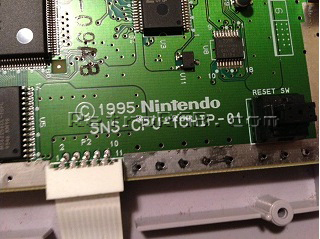
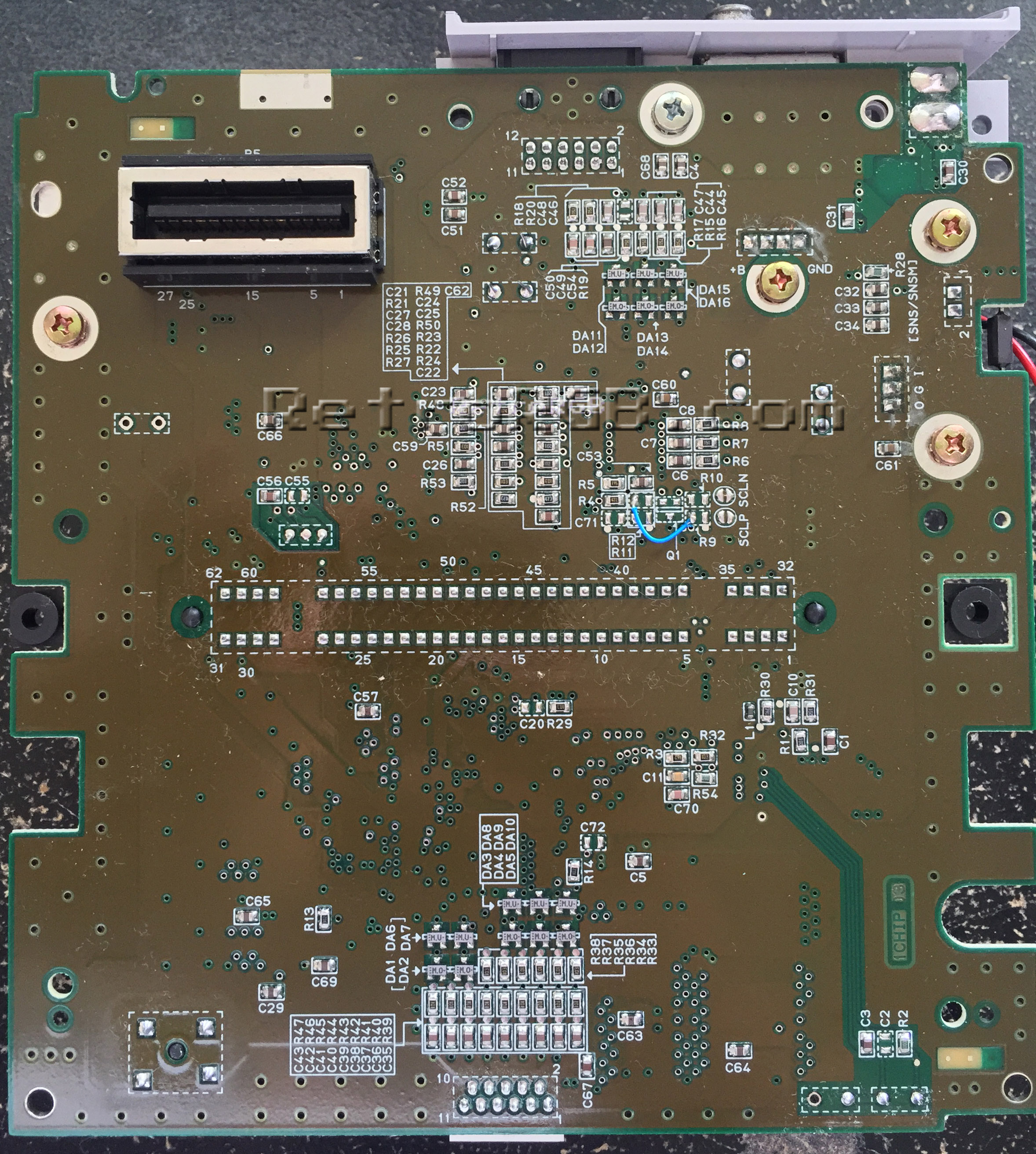
– First you have to “disconnect” the existing RGB connection to the multi-out, in order to allow the new conenction to be made. Remove the motherboard and locate the multi-out pins on the bottom of the board. Right near the multi-out, you’ll find resistors labeled R15, R16 and R17 – These connect RGB to the multi-out. De-solder these resistors to remove the RGB connection to the multi-out. I suggest checking both before and after with a multimeter, to double check that you have the correct resistors and that that connection has been severed. Click for a full-sized view that shows in better detail where the resistors are located:

– Alternatively, you can remove the metal shielding from the top of the motherboard and use a pick or dental tool to carefully lift the three RGB-output legs of the S-RGB chip. Removing the resistors is the preferred way to disconnect the RGB lines, since you can simply replace the resistors if you’d ever like to put the console back to stock. In case you prefer this method, click on each picture for full-sized views:
 |
 |
 |
|
– Now find the following spot on the motherboard:

– Now for the tricky-but-cool part: Take the excess pins left over from the resistors and add them to the RGB holes. You’ll need to hold onto the pins with a pair of pliers or tweezers, as they’ll get really hot. Then, use your soldering iron to heat up each one individually until they slide through the board and stick out a bit. Afterwards, heat them again, adding a bit of solder to each side to secure them in place. Finally, carefully snip off any excess that’s sticking through the top (having some of the pin stick up is fine, as long as they aren’t touching anything else). It should now look like this on the bottom of the board:

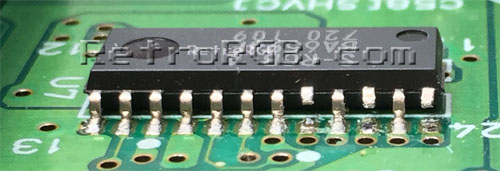
For the record, those holes are direct lines to the RGB-out pins on the main video chip. For reference, here’s the pins on the actual chip (you won’t need to do anything with this, I’m just adding the picture in case anyone’s interested):

– Next, carefully slide the amp over the pins you just installed, solder them in place and cut any excess that’s sticking out. Make sure to align RGB-in on the amp, with RGB on the board and make sure the components on the RGB amp aren’t touching anything on the motherboard:

– Cut the wires to size and solder them to the following points (click on the picture for a full-size version):

– That’s it! Bolt everything back together and try it out. There should be plenty of clearance between the amp/wires and the bottom plastic, but be careful when putting it back, just in case. A quick tip: If your cartridge release lever isn’t as firm as it used to be, you can simply move the spring slightly over. I find moving it just this tiny bit makes a huge difference:

Just a reminder: The 1CHIP-01 and 1CHIP-02 systems already have csync running to pin 3 (sync) on the multi-out, so no modification is needed to get true composite sync. If you have a rare 1CHIP-03 model, you can easily restore csync by adding one wire (click for full-sized). As with ALL SNES systems, this can only be done on NTSC systems, not PAL!:
I strongly recommend you add these three resistors, to ensure the video output looks correct:
– First, solder 750 Ohm resistors to the same places you’d get RGB from the board (if you used my mounting trick above, you can just solder the resistors to the RGB input pins on the THS circuit).
– Then, make sure to solder the RGB wires between the resistors and the board.
– Finally, the other side of all three resistors to ground (click for full-sized):

– For beginners, it must seem strange to tie all the video lines to ground, but as long as the video lines are on the motherboard-side of the resistor, it will work to properly adjust the input brightness to the exact level the 1CHIP SNES should be outputting.
That’s it!
When you’re done, feel free to go back to the main SNES page. If you’d like info on mods for other systems, head to the Getting RGB From Each System page or check out the main page for more retro-awesomeness.