SNES 1CHIP RGB Amp Bypass – Pre-Made THS7374 Chip – NTSC ONLY!!
All model 1 SNES systems (including the 1CHIP) output RGB without a modification. This page shows how to bypass the stock output to improve video quality. Please read the main 1CHIP page for more information.
WARNING: This mod is only for the NTSC 1CHIP systems!!! Using it on a PAL motherboard could damage both the board and the console, since PAL SNES’ have voltage on the sync pin! Also, 2-chip motherboards for other SNES revisions will be different and the pins will not match up. At the moment, there isn’t a good bypass available for the 2-CHIP SNES consoles.
Amp Board:
You’ll need one of the following boards to perform this mod:
Voultar’s THS7374 SNES Amp with S-Video support (Select “1CHIP” from the drop-down menu)
Tools / Parts Needed:
You’ll need a few tools for this mod (more info on the tools can be found in the tools section):
– Pre-Made amp linked above
– Basic soldering skills.
– SNES RGB cable.
– The 4.5mm tool that opens the SNES
– Philips head screwdriver
– Soldering iron / solder
– Thin gauge wire
– Flux or flux pen (not required, but strongly recommended)
– Heatshrink tubing (not required, but recommended)
Modding Service:
This mod is invasive, as you are required to remove components from the motherboard. I don’t recommend this for beginners. If after reading this guide, you decide you’d rather have a professional do it for you, try these services:
USA:
Voultar’s Mod Shop
Retrofixes N64 RGB Mod Service
Canada (Toronto):
Leon Kiriliuk’s Console Mods and restorations
RGB Mod:
– Open the console with the 4.5mm tool. Then remove the cartridge release lever and unplug the front controller ports. Then, unbolt the power switch and then the rest of the philips screws (shown below).

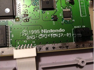
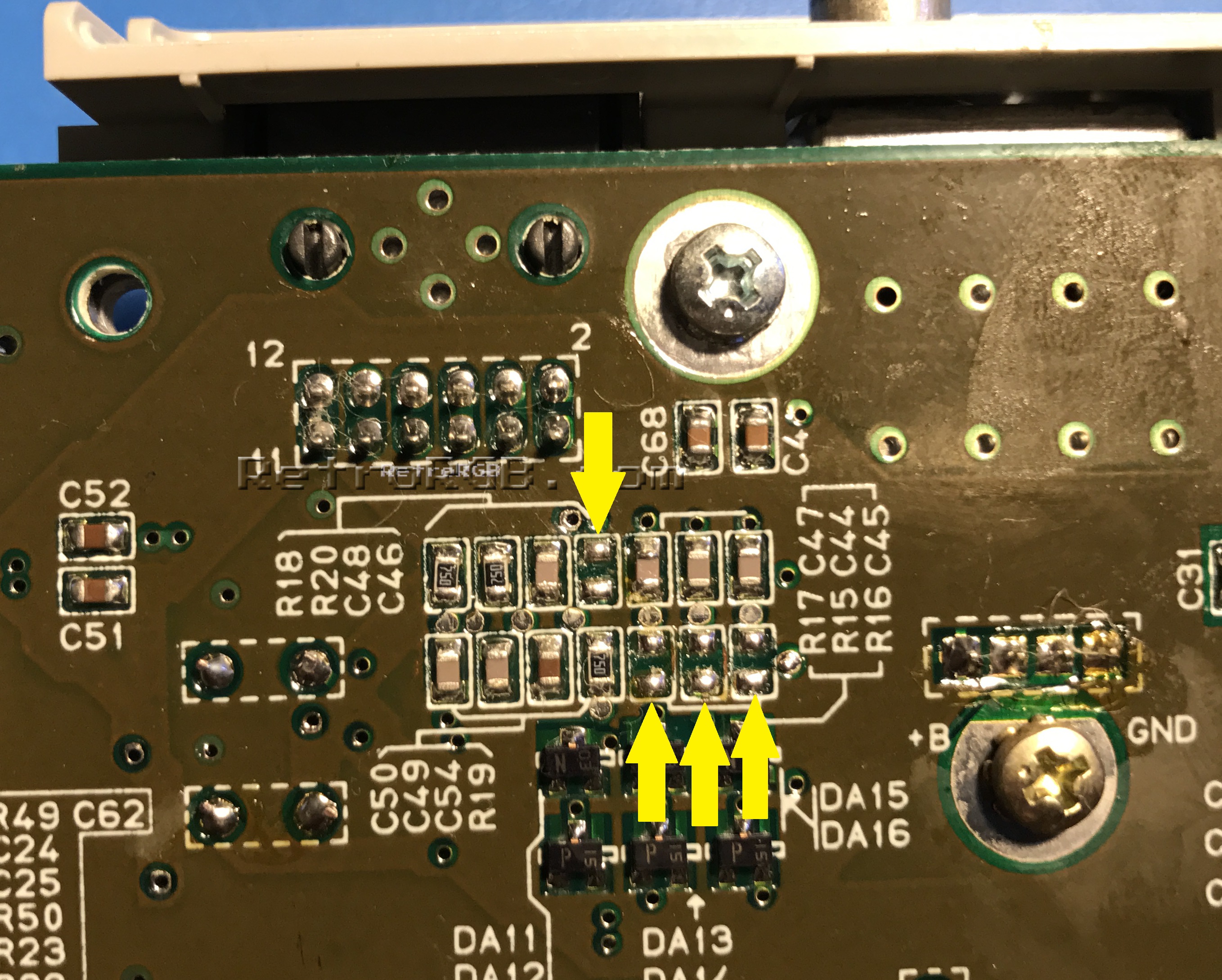
– First you have to “disconnect” the existing RGBs connections to the multi-out, in order to allow the new conenction to be made. Remove the motherboard and locate the multi-out pins on the bottom of the board. Right near the multi-out, you’ll find resistors labeled R15, R16 and R17 and a capacitor labeled C46 – These connect RGBs to the multi-out. De-solder these components to remove the RGB connection to the multi-out. I suggest checking both before and after with a multimeter, to double check that you have the correct resistors and that that connection has been severed.
As an FYI, if you’re using a 1CHIP-03, C46 will already be missing, so you’ll only need to remove the three resistors. Click for a full-sized image:
Alternative RGB disable points:
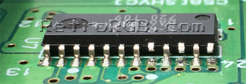
Alternatively, you can remove the metal shielding from the top of the motherboard and use a pick or dental tool to carefully lift the three RGB-output legs of the S-RGB chip. Removing the resistors is the preferred way to disconnect the RGB lines, as it’s much less damaging to the board. In case you prefer this method, click on each picture for full-sized views:
 |
 |
 |
 |
– Now solder wires to the RGBs via’s (holes) that are near the cartridge port. R6, R7, R8 and R9 are RGBs, respectively. I strongly recommend using flux on these via’s!!! Seriously, flux will make this much easier and will allow for a stronger connection. Also, make sure the stripped wire isn’t too long, as it will stick out the top of the motherboard – If the wire is too long, it could cause a short on the other side.
After adding the RGB wires, remove the “R9” resistor shown in the picture. If you have a 1CHIP-03, the resistor will already be missing. Click for a full-sized picture:

– Next, add the amp chip to the multi-out and solder all the connections. Depending on the amp you purchase, you may notice some extra pads and some components missing – This is perfectly normal. Most board makers use the same PCB for 1CHIP and SNES Mini consoles and just change the required components. Since all 1CHIP’s already have S-Video run to the board, these components and pads are not needed. Click for full-sized, but please note there is a mistake in these pictures: R9 is still there and it should be removed. I’ll update the pics ASAP.

TTL Sync Jumper (Voultar’s board only)
If you purchased Voultar’s board, you’ll notice a jumper labeled “TTL” on it. That jumper will set the sync type. Here’s both the full explanation and the “layman’s” explanation:
Voultar’s Explanation:
The C-Sync cable that you purchase may or may not have a load resistor on the C-Sync line to attenuate the amplitude making it 75 ohm compatible. My board integrates the attenuation, so only a C-Sync cable that is pass-thru is required. If however, your cable attenuates TTL C-Sync to 75Ohm, or you require a TTL sync level for your device, short the TTL JPR on the board. Shorting the TTL jumper will restore the C-Sync signal back to a TTL logic level.
An easy way to figure it out:
Use a multimeter to check the sync line on your cable and it’s very easy to do this with the board still out: Simply plug in your cable and check between pin 3 on the multi-out and pin 20 on your SCART head. If you get a beep, you’re good. If you get resistance, short the jumper.

This guide will be tweaked and updated soon. Please read the description of each picture that shows the inaccuracies.
That’s it!
When you’re done, feel free to go back to the main SNES page. If you’d like info on mods for other systems, head to the Getting RGB From Each System page or check out the main page for more retro-awesomeness.