SNES Mini RGB – Pre-made THS7374 Amp
This page shows how to use a pre-made RGB Amp to bypass the SNES Mini’s internal encoder and enable RGB (and depending on the board) S-Video as well. The amp you purchase may not look exactly like the one pictured, however the installation will be the same for all unless otherwise noted.
Warning: Make sure this is the right guide for your amp!!!
I strongly recommend this solution over the older mods, but if you already purchased a different (3-channel) amp, please refer to the main SNES Mini RGB mod page and scroll down to find your relative guide: http://www.retrorgb.com/snesminirgb.html
Amp Board:
You’ll need one of the following boards to perform this mod:
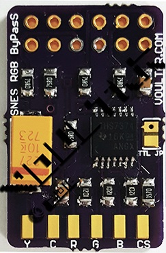
Voultar’s THS7374 SNES Amp with S-Video support
Tools / Parts Needed:
You’ll need a few tools for this mod (more info on the tools can be found in the tools section):
– Pre-Made amp linked above
– Basic soldering skills.
– SNES RGB cable.
– The 4.5mm tool that opens the SNES
– Philips head screwdriver
– Soldering iron / solder
– Thin gauge wire
– Flux or flux pen (not required, but strongly recommended)
– Heatshrink tubing (not required, but recommended)
Modding Service:
If after reading this guide, you decide you’d rather have a professional do it for you, try these services:
USA:
Voultar’s Mod Shop
Retrofixes N64 RGB Mod Service
Canada (Toronto):
Leon Kiriliuk’s Console Mods and restorations
Installation Video:
This is a video demonstrating everything shown in this guide. It may help in your installation:
RGB Mod:
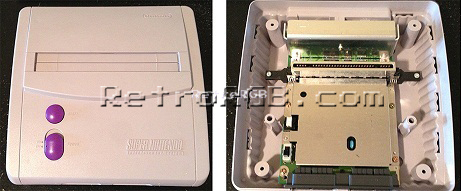
– Open the console and remove the board (pretty much just unscrew everything):
– I’ve actually seen a few SNES Mini’s come from the factory with the two ground pins soldered together. If your system has this, you could either cut the solder in the middle (be really careful not to damage the pins), or use a solder-removing method (de-soldering iron, solder wick, etc). Also, you’ll most likely see some capacitor ends sticking out and interfering with the area you’ll be mounting the board in. I’d just snip all 4:
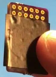
– Next, prepare the pre-made amp board. The bottom of the amp board has no components on it, however I always like to add a piece of non-conductive tape to the bottom, just to be safe. If nothing else, it won’t hurt:
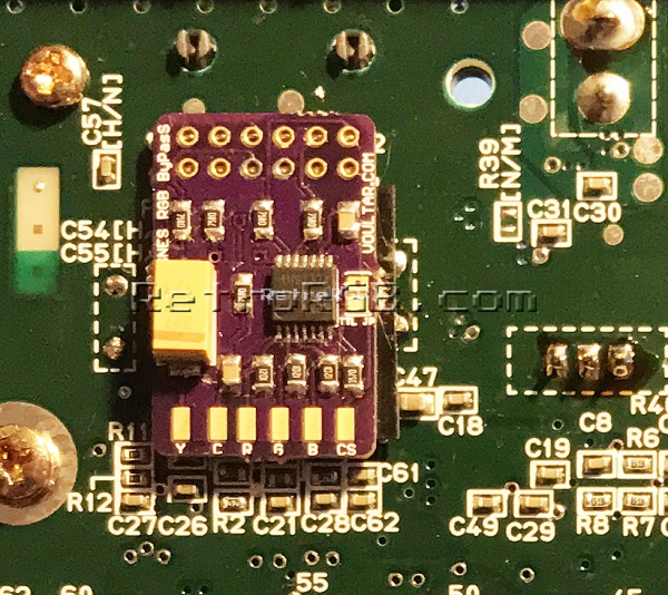
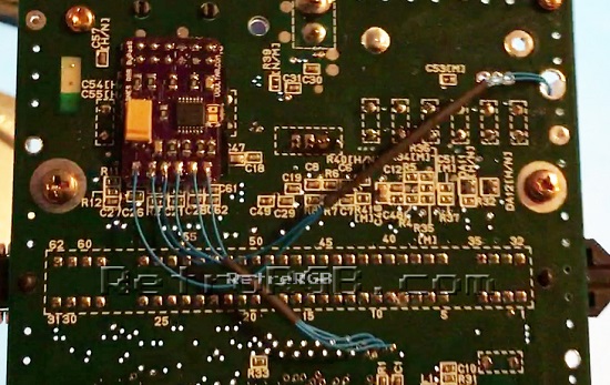
– Now slide the amp over all the multi-out pins. Then carefully solder each pin, making sure not to let the solder spill over onto another pin (flux helps, but isn’t required). Then add solder to all six pads on the bottom (the picture shown is pre-solder):
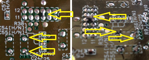
– Next, locate the following spot on the motherboard:
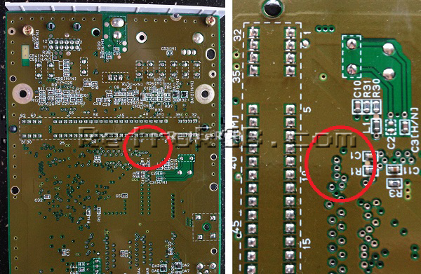
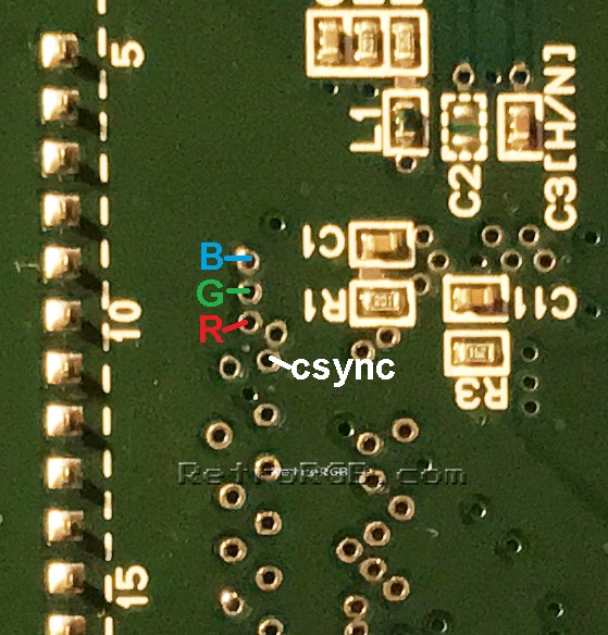
– Solder thin wire to the following “via” holes to get RGBs. I strongly recommend using flux on these via’s!!! Seriously, flux will make this much easier and will allow for a stronger connection. Also, make sure the stripped wire isn’t too long, as it will stick out the top of the motherboard:
– Cut the wires to length and solder them to the corresponding RGBs pads on the amp. I also like to add a bit of heat shrink tubing, just to keep the wires neat. Your installation should now look like this:
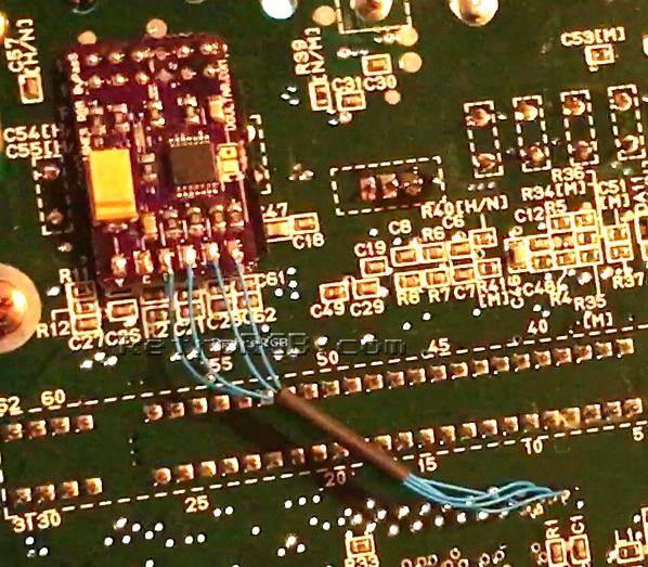
If your board only supports RGB, or if you don’t plan on using S-Video, that’s it! Seriously, just four wires and you’re done! That’s one of the reasons why this is my favorite mod for the SNES Mini.
TTL Sync Jumper (Voultar’s board only)
If you purchased Voultar’s board, you’ll notice a jumper labeled “TTL” on it. That jumper will set the sync type. Here’s both the full explanation and the “layman’s” explanation:
Voultar’s Explanation:
The C-Sync cable that you purchase may or may not have a load resistor on the C-Sync line to attenuate the amplitude making it 75 ohm compatible. My board integrates the attenuation, so only a C-Sync cable that is pass-thru is required. If however, your cable attenuates TTL C-Sync to 75Ohm, or you require a TTL sync level for your device, short the TTL JPR on the board. Shorting the TTL jumper will restore the C-Sync signal back to a TTL logic level.
An easy way to figure it out:
Use a multimeter to check the sync line on your cable and it’s very easy to do this with the board still out: Simply plug in your cable and check between pin 3 on the multi-out and pin 20 on your SCART head. If you get a beep, you’re good. If you get resistance, short the jumper.

S-Video Installation
If your amp board supports S-Video as well, you’ll need to solder two more wires to the board.
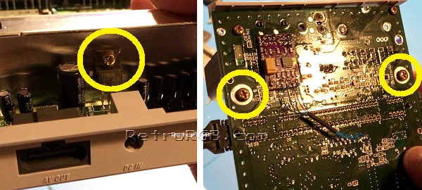
– Start by removing the screw that attaches the voltage regulator to the heatsink, then remove the two screws on the bottom of the motherboard that are holding the heatsink in place.
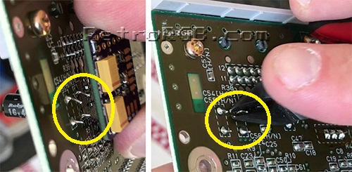
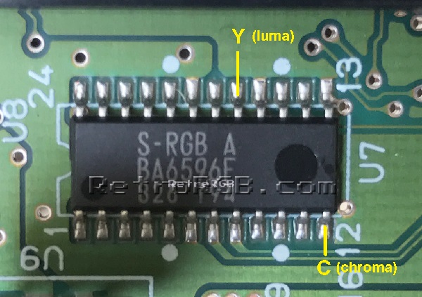
– Then, find the S-RGB chip that’s right next to the cartridge port and solder one wire to luma and the other to chroma. This is another scenario where flux is extremely helpful!
– I like to add a small amount of heatshrink tubing to the wires, then bolt the heatsink on over it. Please note: The wires are NOT being pinched by the heatsink! There is space between the heatsink and motherboard and I find that the two Y&C wires fit nicely underneath:
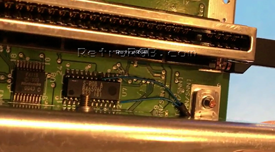
– Lastly, run the Y/C wires through the hole in the bottom of the motherboard (as shown on the right below) and solder them to the board. Once again, I like using heatshrink tubing to keep it as neat as possible:
Finished
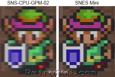
This is a great mod for the SNES Mini. The THS7374 chip is extremely sharp and the video output looks amazing. Check out the difference from an average (non-1CHIP) SNES 1 to a SNES Mini (there are many more pictures on the SNES Version Compare page):
When you’re done, feel free to go back to the main SNES page. If you’d like info on mods for other systems, head to the Getting RGB From Each System page or check out the main page for more retro-awesomeness.